Please click here to download the NICEFLOW-MESH brochure.
Features
- NICEFLOW-MESH is a fully integrated toolbox used during the pre-processing step (mesh generation).
- NICEFLOW-MESH is an advanced and powerful unstructured grid generator for complex geometries.
- Easy-to-use wizard based interface that guides the user through the meshing process.
- Full compatibility with common CAO files formats (IGES, STEP, STL, CGNS, MESH, MSH, CRD).
- Hex to Tet mesh converter.
- Specific (user defined) surface and volumetric mesh adaptations are allowed during the mesh generation process.
- Automatic structured boundary layer mesh generator enables to handle efficiently the collision of several layers.
- Structured (extruded) mesh generator : meshing of analytic shapes, volumetric mesh extrusion along a boundary.
- Single node displacement, nodes fusion and local mesh “reparation” (automatic or manual operations).
- Last generation surface and volumetric mesh optimization algorithms.
- Intelligent mesh for steady or transient simulations using surface and volumetric mesh adaptation processes (automatic).
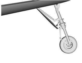
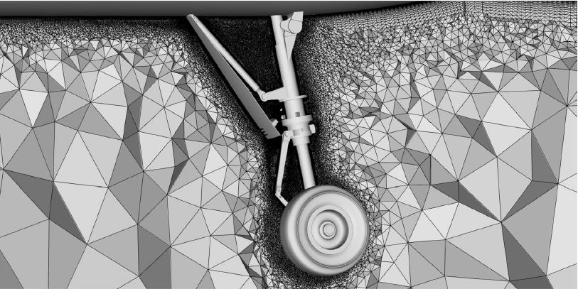
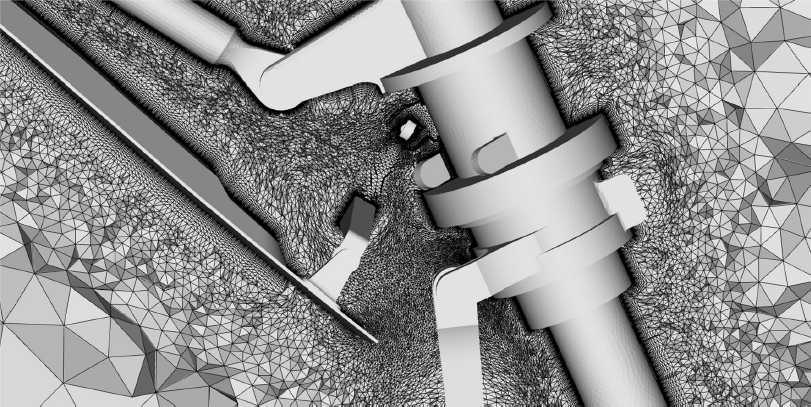
[spoiler style=”2″ title=”Mesh generation process including boundary layer: landing gear geometry”]
Below an example of mesh generation process on complex geometries, including structured boundary layers.This geometry is extremely complex with several geometric details and presents many boundary layer collisions. It points out the robustness of the algorithm to handle geometry configurations representative of industrial applications. The surface mesh is composed of 404,642 vertices and 809,320 triangles. The BL parameters are the following: the initial BL spacing is set to 10−4 and the growth rate is set to 1.2. The initial number of active nodes for the BL generation is 404,230.The algorithm starts from an initial unstructured volume mesh composed of 3,671,082 vertices and 20,586,391 tetrahedra.
[/spoiler]
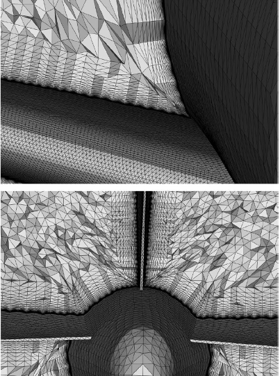
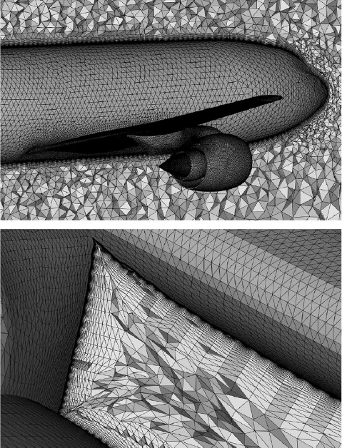
[spoiler style=”2″ title=”Mesh generation process including boundary layer: Wing–body–tail–nacelle meshes”]
The second test case is a wing–body–tail–nacelle configuration with high-quality isotropic unstructured triangular faces on the surface. This case was chosen as it has more overall complexity and multiple concave and merging regions. It also has considerably more surface faces and results in a large number of tetrahedra in the BL region. The initial surface mesh is depicted below on the pictures. The surface mesh is composed of 245,472 vertices and 490,936 triangles. The BL parameters are the following: the initial BL spacing is set to 10−4 and the growth rate is set to 1.2.
[row class=””]
[column size=”1/2″ center=”no” class=””]
[/column]
[column size=”1/2″ center=”no” class=””]
[/column]
[/row]
[/spoiler]
If you want an estimate or a free trial of our software please send us a message!